|
|
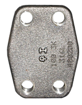
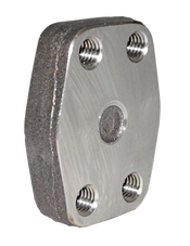
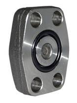
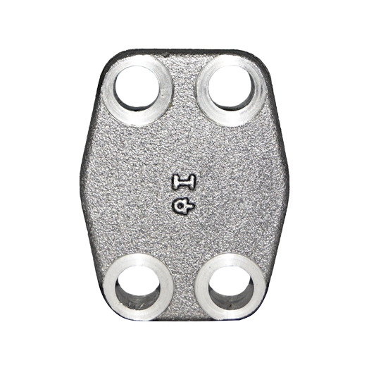
SAE Blind flanges are flanges made in the standards of the SAE J518 / ISO6162. They are mostly used for high-pressure systems and are available in the 3000 and 6000 series. These flanges are produced in sizes ranging from 3/8 inches to 5 inches. They are also called Code 61 flange and code 62 flanges with a working pressure of 3000 PSI and 6000 PSI. They are used for various purposes and can be made from different materials like steel and stainless steel. Blind flanges stand out from the flanges pack as it is designed not to have a drilled hole in the centre. Rather than joining two pipes that most flanges do, a blind flange is used to block a pipe or nozzle currently not in use. |
Material Specification |
|
Working Pressure |
|
Size |
|
Face Type |
|
1. What are SAE Blind Flanges?
|
SAE Blind Flanges are hydraulic flanges that are one of the hydraulic systems tools used to block the passage of oil and other fluids. Unlike other flanges, they have no hole in the middle because they are used to seal the pipes' end. This explains the name by which the flange is called. Despite not having a bored center like others, a blind flange has the same structural structures as the other flanges. For example, the SAE blind uses a similar bolting pattern and face type with other flanges.
They are easily installed and disassembled for easy access to the internal parts of the hydraulic systems. Also, an SAE Blind flange is used for the sealing of nozzles openings. Nozzles are used in pressure vessels for connection to other components. When joining these vessels to other components, flanges are used to seal the connection correctly. The flange type used here can be SAE blind flanges. An SAE Blind flange is preferred to a cap because it has bolts which make it easy to work on. |
Blind flanges are solid flanges with a circular shape. They have bolt holes distributed evenly around the surface area of the flange. The blind flange has lots of sealing faces. They include a flat face and o-ring face.
2. What are the manufacturing methods for SAE Blind Flanges?
|
SAE Blind flanges are made using these four methods – casting and forging, medium plate cutting, forging, and casting. The two main methods are forging and casting. Both forged and casted flanges are suitable, however, each has its downsides. Here’s an explanation of these flange types:
|
3. What are the advantages of SAE Blind Flanges?
|
The SAE Blind Flange primarily performs the function of separating the medium of production. They are also used to seal the pipe ends to avoid leakage of fluids. Blind flanges generally play major functions in hydraulic systems and steam pipelines. More so, SAE Blind flanges can withstand a working pressure of up to 6000 PSI.
They are very easy to install and disassemble, and they simplify the process of working on an internal component of the systems it’s connected to. A blind plug can be used alongside the blind plug and the end cap to block the pipe's fluid flow. During installation, a blind flange is bolted to the pipe flange in the connection. Because the blind flange has no drilled hole in the centre, it stops fluid flow in the pipe. This is useful when general maintenance needs to be carried out and a section of the connection needs to be worked upon. The flange plug is the male fitting that helps close the flow of fluid in a pipe when connected to the female flange body. |
4. The installation process for SAE Blind Flange
The installation process for an SAE Blind Flange is as follows:
STEP 1
Carefully inspect the flange and the surface area for any sign of dirt or damage. Contamination of the surface of the flange can cause damage to the flange within a short period. Therefore, you have to ensure the area is free from any form of contaminants before the installation process begins. This will enable the system to work effectively and efficiently.
STEP 2
Place the flange in the right position using the dimension procedure well. Then, the O-ring can be inserted on the female flange groove.
STEP 3
After inserting the O-ring, place the washer and cap screws on the seal and insert bolts in the holes.
STEP 4
When tightening the bolts, it is advisable you hand-tighten them to avoid over-tightening or any other problem for the flange. Also, remember to tighten according to the torque value.
The table below shows the torque value for each series of the SAE Blind Flange:
Torque value for 3000 PSI
|
Torque value for 6000 PSI
|
SAE BLIND flanges catalogue


