|
|
|
Material Specification |
|
Connection Type |
|
Size |
|
Working Pressure |
|
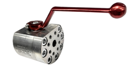
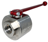
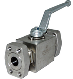
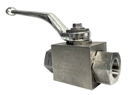
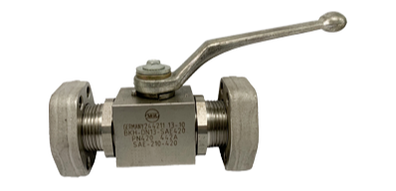
Flange end ball valves are designed following the SAE 3000 (ISO 6162-1) and SAE 6000 (SAE 6162-2) standards. Flange end ball valves are two-way ball valves with an SAE flange connection feature made for use in hydraulic systems. The flange end ball valve is designed in three models – BKH, KH, and MKH.
They are made from carbon steel and stainless steel SS316 materials and sizes available are 1/8” to 3”. It is designed in a quarter turn type way and has a working pressure ranging from 210 to 420 bars. The flange end is one of the common connection type used for the hydraulic system. Generally, it is used as a controlling device for fluids in the oil and gas industry.
They are made from carbon steel and stainless steel SS316 materials and sizes available are 1/8” to 3”. It is designed in a quarter turn type way and has a working pressure ranging from 210 to 420 bars. The flange end is one of the common connection type used for the hydraulic system. Generally, it is used as a controlling device for fluids in the oil and gas industry.
1. What are Flange End Ball Valves?
|
Ball valves are quarter-turn valves with a perforated ball device installed in it which controls the flow of fluids through it. Flange end ball valves are two-way ball valves designed with the flange connection component mostly used in hydraulic systems. They are mostly used for flow and pressure control in hydraulic systems and the oil and gas industry.
Flange end ball valves are made in line with the standards of SAE 3000 (ISO 6162-1) and SAE 6000 (ISO 6162-1). SAE Flanges are very easy to install and remove whenever the user needs to do so. More so, they have just one sealing point between the flanged joint and piping lines. The easiest connection for installing and disassembling pipelines is provided with the flange end ball valves. The valve is often attached to pipe flanges with numerous bolts, this makes it easy to quickly and easily install and uninstall the connection. |
2. What is Flange End Ball Valve made of?
Flange end ball valves are made mainly from stainless steel SS316 and carbon steel elements. A material combination code has been formulated for easy identification of the ball valve parts for users and allows customization of the design for the intended application easily carried out. The table below shows the material combination code for stainless steel and carbon steel flange end ball valves:
|
|
|
The above table shows the material combination code for the carbon steel flange end ball valve.
|
The next table shows the material combination code for the stainless steel flange end ball valve.
|
3. How many types of Flange End Ball Valves body designs are available?
|
The standard flange end ball valves are produced in three common body designs. These designs are BKH, KH, and MKH. The flange end ball valves designed with the BKH/BKHP design (square body) have a size ranging from 1/2” to 1”, while the MKHP valves (round or hexagon body) has a size between 1 1/4” and 2”. The working pressures for both designs are 210 Bars (3000 PSI) and 420 Bars (6000 PSI) respectively. Also, the BKH and MKH valves have elongated male threads from the connection points of SAE adaptors on both ends of the ball valve. This elongation gives the valve a longer length than the general valve body designs. (SAE adapters use the metric or UNC thread connection types).
|
The KH body design is a newly developed concept from MHA-Zentgraf. Flange end ball valves in this design are specially made with an SAE connection metric. The body comes as a single without adapter assembly. This attachment is a pro for the design as the point of assembly is reduced which also ensures maximum tightness of components. They are shorter in length than the BKH and MKH designs. The sizes range from 1/2” to 3”. The working pressures for the KH design are 210 Bar (3000 PSI) and 420 Bar (6000 PSI) and the design can also accommodate dual working pressures.
Here’s a summary chart for the flange end ball valve body designs explained above:
Here’s a summary chart for the flange end ball valve body designs explained above:
Valve Type |
|
|
|
Working Pressure |
|
|
|
Diameter Size |
|
|
|
Connection Type |
|
|
|
Body Design |
|
|
|
4. How does a Flange End Ball Valve works?
|
The flange end ball valve adaptor has a flat side flange. However, an O-ring side in the SAE standard is needed for connection to the valve adaptor and movement of fluids. After fixing the flat side flange and O-ring side together, 4 Allan cap screws and washers are needed to tighten up the connection.
The main components of the flange end ball include body, seat, ball, cover, and stem. The flange can be operated manually, electrically, or by pneumatic actuators. For manual operation, the lever of the valve is placed in strategic angles for easy opening and closing. For actuators, the size of the right actuators for use is not fixed, however, it follows the standards of the international body (ISO). A flanged end ball valve is an important part of the flow in systems. Any malfunctioning from this device can cause leakage and corrosion subsequently. |
5. What is the proper way to install a High Pressure Ball Valve?
To successfully install a complete set of flange end ball valve to a pipeline in a hydraulic system, you will need the following:
- 8 pieces of Allan cap screws
- 8 pieces of Spring washer
- 2 pieces of O-ring seal
- A ball valve with an SAE flange adapter
- An SAE O-ring side flange.
|
One important factor to have considered when designing the flange end ball valve is the Flow rate. The valve coefficient (Cv) is defined as the maximum flow rate for a valve at the current flow rate. It highlights the connection between a drop in pressure with the flow rate.
Flow Coefficient (Kv): The flow coefficient of a machine is a measurement of the efficiency at the current fluid flow. It is the flow rate of water occurring at a temperature level between 5⁰C (40⁰F) and 40⁰C (104⁰F) resulting in loss of pressure measured as 0.1 MPa (14.5 PSI, 1 bar). Accurate calculation of the flow coefficient leads to an increased efficiency rating for the system. |
Cv (gal/min) |
Kv (m3/h) |
Nominal Diameter (mm) |
Nominal Diameter (inch) |
22,6 |
19,4 |
15 |
1/2” |
53,0 |
45,6 |
20 |
3/4” |
83,1 |
71,5 |
25 |
1” |
122,1 |
105 |
32 |
1 1/4” |
197,1 |
170 |
40 |
1 1/2” |
319,8 |
275 |
50 |
2” |
589,5 |
507 |
65 |
2 1/2” |
1052,3 |
905 |
80 |
3” |
1644,2 |
1414 |
100 |
4” |
2746,5 |
2362 |
125 |
5” |
4295,3 |
3694 |
150 |
6” |
SAE FLENGE END BALL VALVES CATALOGUE

