
|
|
|
Configuration |
|
Material Specification |
|
Series |
|
Size |
|
Connection Type |
|
Hydraulic SAE Flanges also are known as SAE Codes 61, or SAE Codes 62 are produced according to the SAE J518/ ISO 6162 specifications. The codes 61 and 62 depict 3000 PSI and 6000 PSI working pressure, respectively. They serve as an alternative means for fixing components like pipes, hoses, tubes, machines, and other equipment.
Steel is the significant raw material used in the production of hydraulic SAE Flanges, and carbon content of less than 0.30% is combined with it. However, another material that could be used in its production is a galvanized flange substance or stainless steel (SS316).
Steel is the significant raw material used in the production of hydraulic SAE Flanges, and carbon content of less than 0.30% is combined with it. However, another material that could be used in its production is a galvanized flange substance or stainless steel (SS316).
1. What is an SAE Flange?
|
Hydraulic SAE Flange is a type of hydraulic flange mostly used in hydraulic oil systems. The term ‘SAE’ represents the Society of Automotive Engineers, a body established in 1905 in charge of developing standards for various industries in the engineering field. The flange has 4-bolt connection openings and is widely used across the globe.
Hydraulic SAE Flanges serve various purposes. With the connection sealed tightly to ensure no leakage, the flange is capable of working with high pressures and large size machines. Moreover, the design of the hydraulic SAE flanges has lots of advantages which are as follows:
|
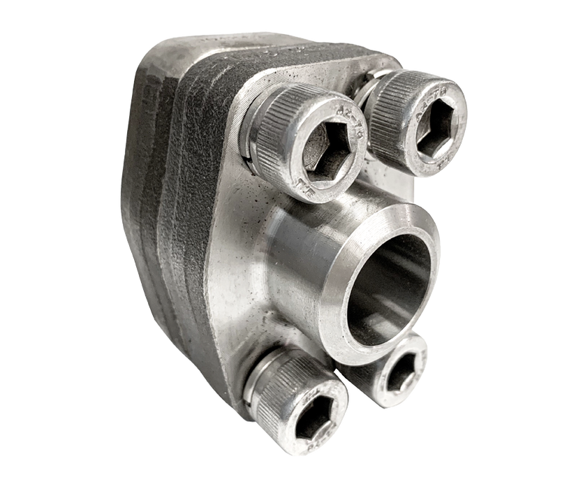
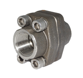
SAE Flange SS316 Butt Weld SCH80 3000#
|
2. What are SAE Flange bolts used for?
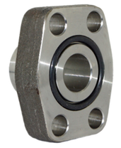
SAE Flange O-ring Side
|
The specifications of the flange conform to the standards of the ISO 6162 and SAE J518. Also, it has 4 holes for bolts connection with the metric or UNC thread. These bolts connected to the flange are in various grades. The grade types are explained below:
|
The hydraulic SAE flange also has a metric or UNC thread. The metric thread is classified as the most accepted and used screw thread. It was agreed as an international standard after the establishment of the International Organization for Standardization (ISO) in 1947. It is available in various sizes.
The UNC thread on the other hand uses an inch fraction dimension rather than the millimeter value used by the metric thread. It is used widely for diverse thread fasteners including bolts and nuts.
The hydraulic SAE flange comes with a combination of O-ring face, O-ring groove, cap, screws, flat face, and 4 washers. SAE flanges are sealed with a static face seal. This static face seal uses a high durometer O-ring. For the O-ring sealing to be leakage free, the flat face and O-ring are compressed together and this gives a reliable soft sealing.
Description |
Viton 90 |
NBR 70 / 90 |
Equivalent |
FKM |
BUNA-N |
Temperature Range (⁰C) |
-26 ⁰C to 205 ⁰C |
-34 ⁰C to 121 ⁰C |
Non-recommended Application |
|
|
Recommended Application |
|
|
The table above shows the materials used for seals of flanges.
3. How can you tell the difference between code 61 and code 62 flanges?
The hydraulic SAE Flange is also called SAE code 61 and SAE code 62. These terms may mean the same thing, however, they are two distinct factors. The table below shows the difference between the code designs:
|
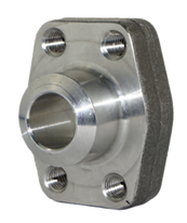
SAE Flange Flat Side
|
4. How can pipes be attached to SAE Flanges?
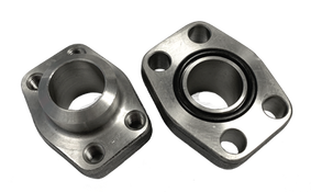
SAE Flange O-Ring Side
|
Hydraulic SAE flanges can be easily connected, disconnected, and used for maintenance purposes through the zero-clearance assembly. Also, the SAE flanges can be attached to different holes on systems easily with the infinite positioning feature it has.
The flange can be connected using different methods
|
With these two ends being used, there is a maximized reliability of the system. Also, it is essential to state here that maintenance checks should be done periodically to replace or repair the faulty part (as the case may be). With these checks, the system will work effectively and efficiently.
5. How can you install an hydraulic SAE Flange?
For safety, while using hydraulic SAE Flanges, it is important to understand the installation process well and the torque range. Due to the use of hydraulic SAE Flanges on a hydraulic system with a high-pressure level, you have to ensure proper fitting is done before the installation process begins. Also, you have to follow the installation procedures keenly because an error in this process can cause leakage of oils. This can as well reduce the efficiency and general performance of the system.
The installation of an SAE Flange can be done using these following steps:
STEP 1
The first step is for you to ensure the components parts of the system and flange is free from contamination. Any form of substance that can affect the flange or lead to its damage should be thoroughly cleaned out.
Also, lubricate the flange on the O-ring part with harmless lubricant.
STEP 2
Place the flange at the rightful position. This should be done before the O-ring seal is inserted into the female flange groove.
Then, insert the washer on the cap screws and bolts on their holes.
STEP 3
After successful insertion of the O-ring, tighten the bolts placed on their holes with your hands. Then, rotate the screws diagonally till the right torque value is reached.
The table below shows the torque value for each flange size:
Table value for 3000 Code 61
|
Table value for 6000 Code 62
|
HYDRAULIC SAE flanges catalogue
Let's get together
|
|
SAE Flanges Threaded Complete Set
|