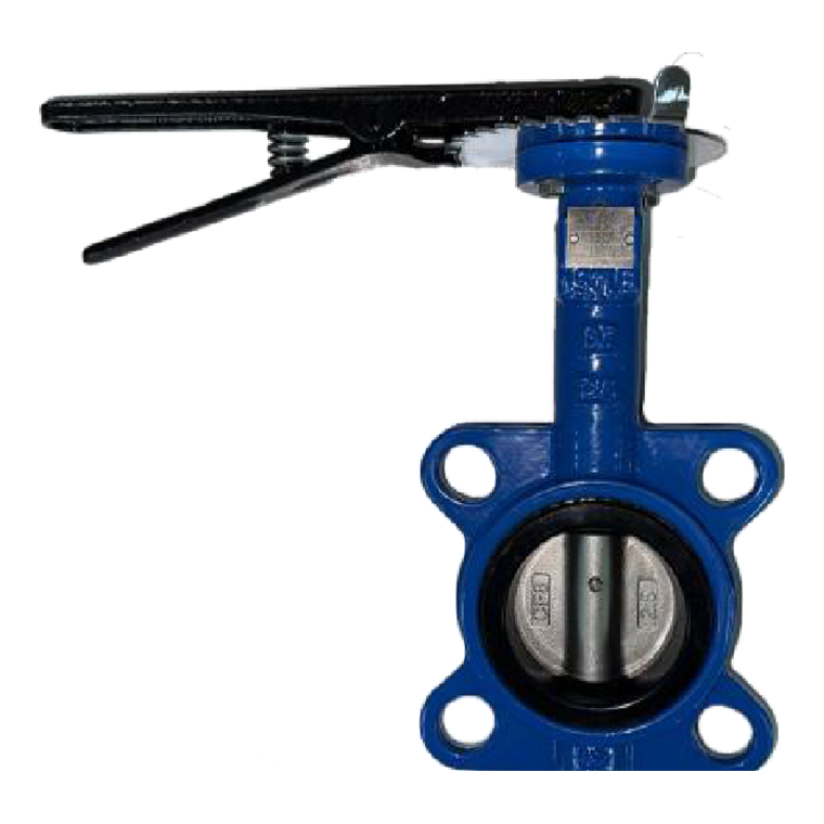
A quarter-turn Wafer type butterfly valve in 1½″–6″ (DN40–DN150) with a Ductile iron body, a CF8 disc and an EPDM seat. SS410 shaft with an SS304 pin and an NBR O-ring. Rated 150 PSI at −30 °C to 120 °C, built to API 609 and tested to API 598.
Send the size, the body style and the fluid — the seat governs, and quotes go out within 2 working hours.
| Body style | Wafer type |
|---|---|
| Ends | Wafer — PN10, PN16, ANSI 150# or JIS 10K |
| Size | Stocked 2″–4″ (DN50–DN100); catalogue 1½″–6″ |
| Body | Ductile iron |
| Disc | CF8 |
| Seat | EPDM |
| Shaft | SS410, SS304 pin |
| Pressure | 150 PSI |
| Temperature | −30 °C to 120 °C |
| Operation | Quarter turn, lever |
A quarter turn. The disc rotates in the flow; it never leaves it.
A round disc on a shaft across the bore. A quarter turn on the lever takes the disc from parallel with the flow to square across it, pressing its rim into the EPDM liner. That liner is what seals — the seat is the pressure boundary, not the body. The body only holds the liner in place.
Because the disc stays in the flow even when fully open, a butterfly valve always restricts a little — unlike a gate valve, which gives a straight bore. What you get in exchange is far shorter, far lighter and far cheaper at large bore, and a quarter-turn action.
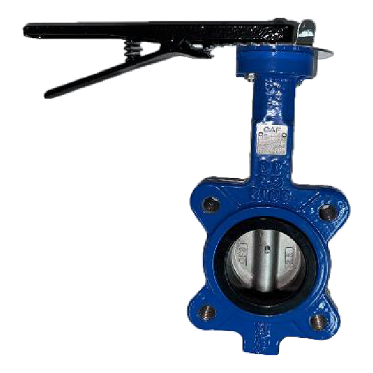
The body is clamped between the two pipe flanges. That is why a wafer valve cannot hold pressure with one flange removed — for that you need the Ductile iron lug.
EPDM suits water, hot water and air, and is poor with mineral oil. If your fluid needs something else, say so before you order — a different liner is a specification, not a modification.
We checked the two published lists against each other and they are identical part for part and material for material. The bodies differ; nothing inside them does.
It drives the disc through an SS304 pin and is sealed by the NBR O-ring, running in polymer bushings that take the side load.
It bends rather than snapping if someone puts a bar on it — though the right answer on the larger sizes is a gearbox, since torque rises sharply through the last part of the stroke.
It is the same on both body styles. Specify a gearbox once and it fits either.
Photographs of the stocked item, not renders.
It is visible from both faces of the valve. That is the part that seals, and the part that has to suit your fluid.
You can hold the disc part open for coarse regulation, but a butterfly valve is not a precision throttling valve — most of the flow change happens in the last 30 degrees.
That is the gearbox or actuator interface, and it is the same size on wafer and lug.
Everything that goes on a purchase order.
| Item | Value |
|---|---|
| Size range | Stocked 2″–4″ (DN50–DN100) · catalogue publishes 1½″–6″ (DN40–DN150) |
| Body style | Wafer type |
| Ends and drilling | Wafer — PN10, PN16, ANSI 150# or JIS 10K |
| Body | Ductile iron |
| Disc | CF8 — cast 304 stainless |
| Seat | EPDM — and it is the pressure boundary |
| Shaft | SS410, pinned with SS304, in polymer bushings |
| Shaft seal | NBR O-ring |
| Handle | Ductile iron lever with a notched locking plate |
| Working pressure | 150 PSI per the specification box · nominal 1.0 MPa per the test table — design to 150 PSI unless we confirm otherwise |
| Shell test | 1.5 MPa |
| Seal test | 1.1 MPa |
| Working temperature | −30 °C to 120 °C |
| Design · face-to-face · test | API 609 · API 609 · API 598 |
| Operation | Quarter turn; the top flange takes a gearbox or actuator |
| Parts in the list | 8 — identical on both body styles |
| Stock | Held in Malaysia or Singapore |
The features box says 150 PSI; the Main Technical Parameter table gives a nominal pressure of 1.0 MPa. We print both as they stand and advise designing to the lower one unless we confirm with the factory.
120 °C is the EPDM limit. The iron casting goes well beyond it; the liner does not.
It means the body length follows the standard, so a replacement from another maker in the same body style drops into the same gap.
7 sizes. Millimetres. The DN column stays put while the table scrolls.
Read face-to-face L for the gap the valve needs, H for the height including the lever, C for how far the disc protrudes, and the top flange columns if you are fitting a gearbox.
| DN | Size | Height H | Disc C | L0 (a) | L0 (b) | PN10 D1 | PN10 n-d1 | PN16 D1 | PN16 n-d1 | ANSI 150 D1 | ANSI 150 n-d1 | JIS 10K D1 | JIS 10K n-d1 |
|---|---|---|---|---|---|---|---|---|---|---|---|---|---|
| DN40 | 1½″ | 241 | 42 | 240.4 | 220 | 110 | 4-18 | 110 | 4-18 | 98.5 | 4-16 | 105 | 4-19 |
| DN50 | 2″ | 241 | 42 | 240.4 | 220 | 125 | 4-18 | 125 | 4-18 | 120.5 | 4-19 | 120 | 4-19 |
| DN65 | 2½″ | 264 | 44.7 | 240.4 | 220 | 145 | 4-18 | 145 | 4-18 | 139.5 | 4-19 | 140 | 4-19 |
| DN80 | 3″ | 276 | 45.2 | 240.4 | 220 | 160 | 4(8)-18 | 160 | 4(8)-18 | 152.5 | 4-19 | 150 | 4(8)-19 |
| DN100 | 4″ | 314 | 52.1 | 280.8 | 255 | 180 | 4(8)-18 | 180 | 4(8)-18 | 190.5 | 4-19 | 175 | 4(8)-19 |
| DN125 | 5″ | 310 | 54.4 | 280.8 | 260 | 210 | 4(8)-18 | 210 | 4(8)-18 | 216 | 4-22 | 210 | 4(8)-23 |
| DN150 | 6″ | 365 | 55.8 | 280.8 | 260 | 240 | 4(8)-23 | 240 | 4(8)-23 | 241.5 | 4-22 | 240 | 4(8)-23 |
The C column is how far the disc protrudes past the body face when open. On the smaller sizes it comes out past the body. A valve that fits in the run can still fail to open.
D1 is a body diameter to check for clearance. For ANSI 150 at these sizes the bolt circles are 98.4 · 120.7 · 139.7 · 152.4 · 190.5 · 215.9 and 241.3 mm.
ASME B16.5 Class 150 uses 8 bolts from NPS 4 upward; the ANSI column here prints 4 at 4″, 5″ and 6″, as published. On a wafer body those bolts clamp the valve in place — take the count from the flange standard.
4-7 on ø50 up to 3″, 4-9 on ø70 from 4″ up. Specify a gearbox once and it fits either body.
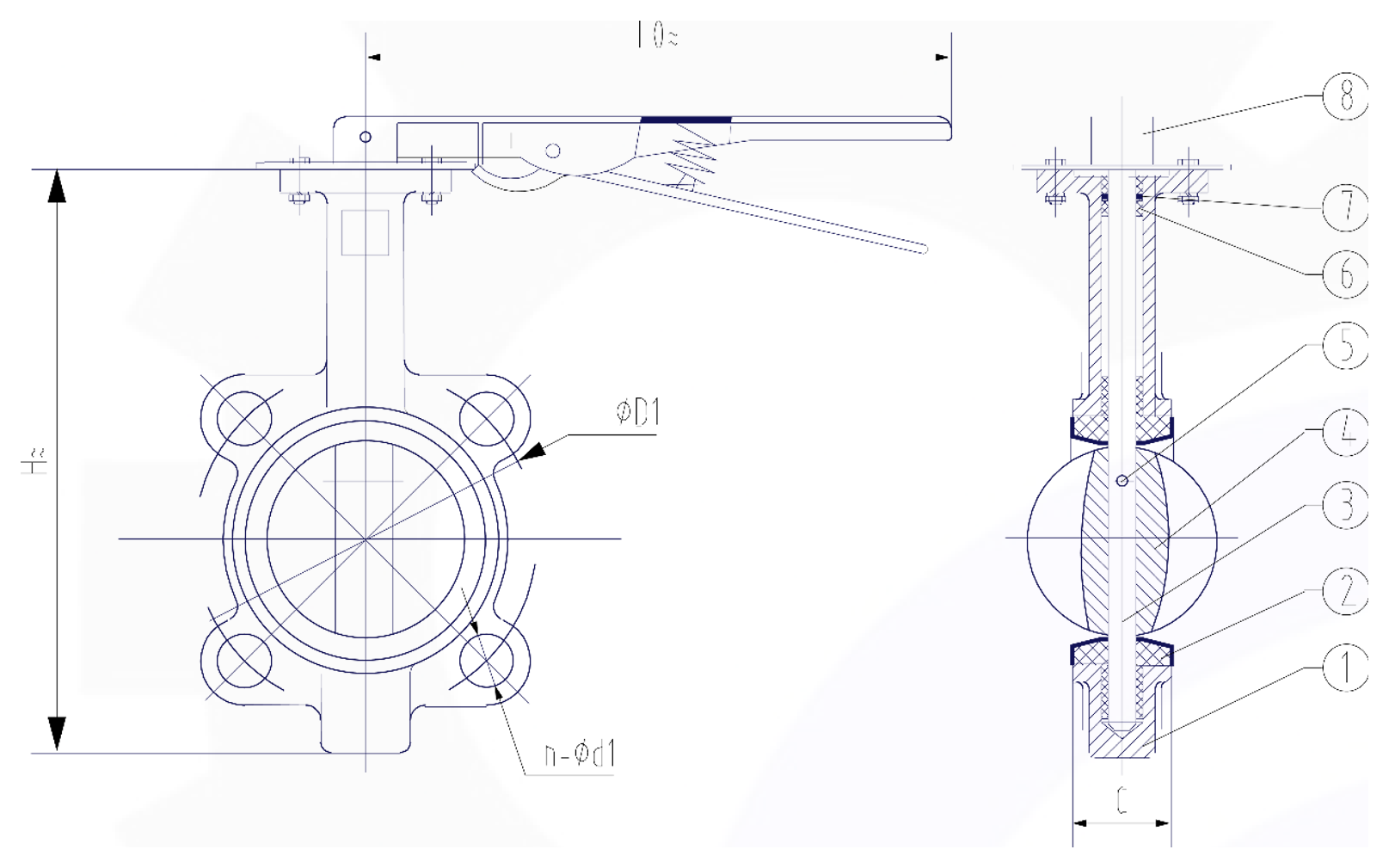
Eight callouts, and eight items in the parts list below — the two match one for one. The dimension letters are the column headings in the size table above: H height, C disc protrusion, L0 lever length, øD1 body diameter, n-ød1 the bolt pattern, and K, E, g, h, z-ød on the top flange. The diagonal square head detail shows the stem-to-gearbox interface.
Callout numbers are the item numbers in the parts list below, and the dimension letters are the column headings in the size table above. Nothing on the drawing is named only there.
The disc presses into the liner, and the liner wraps the bore. The iron body never touches the fluid on the sealing path.
This is a catalogue section, not a manufacturing drawing: no tolerances and no material callouts. Order spares by the item numbers in the parts list.
Eight parts — identical on the wafer and lug bodies.
| No. | Part name | Material |
|---|---|---|
| 1 | Body | Ductile Iron |
| 2 | Seat | EPDM |
| 3 | Shaft | SS410 |
| 4 | Disc | CF8 |
| 5 | Pin | SS304 |
| 6 | Bushing | Polymers |
| 7 | Oring | NBR |
| 8 | Handle Lever | Ductile Iron |
They match the callouts on the sectional drawing above, so a spares order matches the section rather than a description.
Everything else is a casting, the shaft or a fastener. The EPDM seat is the first part to ask about, and the only one that decides fluid compatibility.
CF8 in the bill of materials, SS304 in the part descriptions. Both are the 304 family; we quote both as printed.
If you need to know what touches your fluid, the whole list is above — we have not summarised it.
Factory proof tests. Not a working pressure. Do not design to these figures.
| Item | Value |
|---|---|
| Nominal pressure | 1.0 MPa |
| Shell test | 1.5 MPa |
| Sealing test | 1.1 MPa |
| Working temperature | −30 °C to 120 °C |
| Medium | General oil, gas and water |
This table gives a nominal 1.0 MPa; the catalogue features box says 150 PSI. Both are the factory’s. Design to the lower one unless we confirm otherwise.
Both are factory proof tests. Neither is a figure to work to.
120 °C is the EPDM limit, not the iron’s. If your duty goes past it, the liner is what changes — and that is a specification, not a modification.
Body style first, then material, then the seat.
All four side by side: the comparison table.
A quarter-turn Wafer type butterfly valve in 1½″–6″ (DN40–DN150) with Wafer — PN10, PN16, ANSI 150# or JIS 10K ends, a Ductile iron body, a CF8 disc and an EPDM seat. Rated 150 PSI at −30 °C to 120 °C, built to API 609 and tested to API 598.
No. A wafer body is clamped between two flanges and the bolts pass right through, so it cannot hold pressure with one flange removed. Use the lug type for that.
The seat is EPDM: it suits water, hot water and air, and is poor with mineral oil. The seat is the pressure boundary, so fluid compatibility is decided by the liner, not by the iron body. Tell us the fluid when you ask for a price and we will confirm the liner.
Because the catalogue prints two. The features box says 150 PSI; the Main Technical Parameter table gives a nominal pressure of 1.0 MPa. We print both as they stand. Design to the lower one unless we confirm with the factory.
Coarsely, yes — the lever has a notched locking plate. But most of the flow change happens in the last 30 degrees of the stroke, so it is not a precision throttling valve, and holding the disc slightly open puts full flow velocity across its rim. For real regulation use a globe valve.
Very little length — that is the butterfly valve advantage. What gets missed is disc protrusion: the C column in the dimension table is how far the disc comes past the body face when open. On the smaller sizes it protrudes. A valve that fits in the run can still fail to open.
Yes. The top flange is published — 4-7 on ø50 up to 3″, 4-9 on ø70 from 4″ — with a diagonal square head on the stem. It is the same on wafer and lug bodies, so one gearbox specification fits both.
Take that from the flange standard, not from this table. ASME B16.5 Class 150 uses 4 bolts up to 3″ and 8 from NPS 4 upward. The D1 column in the dimension table is a body diameter to check for clearance, not a bolt circle.
Shell and sealing tests are in the test-pressure table on this page, as printed. Both are factory proof tests, not working pressures — do not design to them.
We hold them in the Singapore and Malaysia warehouses, out within 24 hours of a PO. Quotes within 2 working hours. Send the size, the body style and the fluid.
Related: all butterfly valves · gate valves · ball valves · Y-strainers · our videos on YouTube.