
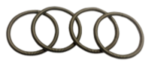


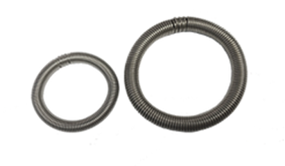
The stainless spring ring that holds a flange on the pipe without welding. The pipe end is faced and grooved, the flange slides on, the ring is stretched into its groove — and the joint carries the axial load and shock with no hot work permit, no weld inspection, and no slag to clean out.
State the pipe OD and wall thickness plus the pipe standard (metric or ANSI) — quotes within 2 working hours.
| Function | Holds the flange & carries the axial load |
|---|---|
| Range | 1/2″–14″ — pipes 26 to 355.6 mm |
| Standards | ISO 6162 (SAE J518) · ISO 6164 |
| Ring material | SS302 only — non-negotiable |
| Pressure | 210–690 bar — by system |
| Wire sections | 4 · 5 · 6 · 8 · 10 · 12 mm |
| Ordered by | Pipe outside diameter, not flange size alone |
Four part-number tables — ISO 6162 and ISO 6164, each in metric and ANSI — are on this page, as printed in the catalogue.
| At a glance | SAE 3000 | SAE 6000 | ISO 6164 |
|---|---|---|---|
| Pressure | 210–350 bar | 420 bar | 210–690 bar |
| Pipe OD | 26–97 mm | 26–66 mm | 60.3–355.6 mm |
| Wall | 6–12 mm | 6–8.5 mm | 11.04–41.4 mm |
| System | Working pressure | Pipe OD | Pipe wall | Flange size |
|---|---|---|---|---|
| SAE 3000 | 210–350 bar | 26–97 mm | 6–12 mm | 1/2″–3″ |
| SAE 6000 | 420 bar | 26–66 mm | 6–8.5 mm | 1/2″–2″ |
| ISO 6164 | 210–690 bar | 60.3–355.6 mm | 11.04–41.4 mm | 2″–12″ |
ISO 6162 (SAE J518) — metric pipe ends
| Flange | Part # | Pipe (OD × wall) | Ring bore D | Wire S |
|---|---|---|---|---|
| 1/2″ | 08 | 26 × 6 | 30 | 4 |
| 3/4″ | 12 | 36 × 8 | 39.3 | 4 |
| 1″ | 16 | 39 × 7.5 | 44 | 5 |
| 1¼″ | 20 | 46 × 8 | 51 | 5 |
| 1½″ | 24 | 56 × 8.5 | 61 | 5 |
| 2″ | 32 | 66 × 8.5 | 71 | 5 |
| 2½″ | 40 | 80 × 10 | 85 | 5 |
| 3″ | 48 | 97 × 12 | 103 | 6 |
ISO 6162 (SAE J518) — ANSI B36.10 / B36.19 pipe ends
| Flange | Part # | Pipe (OD × wall) | Ring bore D | Wire S |
|---|---|---|---|---|
| 1/2″ | 08/21.3 | 21.3 × 7.5 | 25.5 | 4 |
| 3/4″ | 12/26.7 | 26.7 × 7.8 | 30.4 | 4 |
| 1″ | 16/33.4 | 33.4 × 9.1 | 38.4 | 5 |
| 1¼″ | 20/42.2 | 42.2 × 9.7 | 47.4 | 5 |
| 1½″ | 24/48.3 | 48.3 × 10.2 | 53.4 | 5 |
| 2″ | 32/60.3 | 60.3 × 11.1 | 65.2 | 5 |
| 2½″ | 40/73 | 73.0 × 14.02 | 77.9 | 5 |
| 3″ | 48/88.9 | 88.9 × 15.2 | 94.7 | 6 |
Compare those two tables at the same flange size. At 1/2″: metric pipe 26 mm with a 30 mm ring bore; ANSI pipe 21.3 mm with a 25.5 mm ring bore. Different part numbers, and the rings do not interchange. The part code writes the flange size in sixteenths (08 = 1/2″, 32 = 2″), with a /pipe-OD suffix on the ANSI rings.
ISO 6164 — metric pipe ends
| Flange | Part # | Pipe (OD × wall) | Ring bore D | Wire S |
|---|---|---|---|---|
| 2″ | 32 | 66 × 8.5 | 71 | 5 |
| 2½″ | 40 | 80 × 10 | 85 | 5 |
| 3″ | 48 | 97 × 12 | 103 | 6 |
| 4″ | 56 | 115 × 15 | 123 | 8 |
| 4½″ | 60 | 130 × 15 | 138 | 8 |
| 5″ | 64 | 150 × 15 | 158 | 8 |
| 6″ | 80 | 190 × 20 | 200 | 10 |
| 8″ | 88 | 220 × 20 | 231.1 | 12 |
| 10″ | 96 | 250 × 25 | 262 | 12 |
ISO 6164 — ANSI B36.10 / B36.19 pipe ends
| Flange | Part # | Pipe OD | Ring bore D | Wire S |
|---|---|---|---|---|
| 2″ | 32/60.3 | 60.3 | 65.2 | 5 |
| 2½″ | 40/73.0 | 73.0 | 77.9 | 5 |
| 3″ | 48/88.9 | 88.9 | 94.7 | 6 |
| 4″ | 56 | 114.3 | 122.3 | 8 |
| 5″ | 64/141.3 | 141.3 | 149.3 | 8 |
| 6″ | 80/168.3 | 168.3 | 178.3 | 10 |
| 8″ | 88 | 219.1 | 231.1 | 12 |
| 10″ | 160 | 273.0 | 285 | 12 |
| 12″ | 192/323.9 | 323.9 | On request | — |
| 14″ | 224/355.6 | 355.6 | On request | — |
All dimensions in millimetres. The 12″ (323.9 mm) and 14″ (355.6 mm) sizes are quoted on request.
| Measurement | What it tells you |
|---|---|
| Wire section 4 mm | 1/2″ or 3/4″ |
| Wire section 5 mm | 1″ to 2½″ |
| Wire section 6 mm | 3″ |
| Wire section 8, 10, 12 mm | ISO 6164 sizes 4″ and up |
| Ring bore D | Cross-reference to the dimension tables above |
| Pipe OD + wall | Direct lookup in the part number tables |
| Component | Material options | Selection criteria |
|---|---|---|
| Ring | SS302 only | Non-negotiable — buried in the groove, its corrosion cannot be inspected |
| Flange | Hot-dip galvanised carbon steel, electro-zinced carbon steel, stainless steel, titanium | External environment exposure |
| Seal | Viton (FPM) or NBR; fire-safe option for process piping | Medium type and operating temperature |
| Pipe | Materials with elongation ≥20% | Must accommodate the groove-induced local strain |
Why stainless-only rings? Because once the flange is bolted up, the ring is buried in the groove and cannot be inspected. Corrosion on a carbon steel ring would be a hidden failure — which is why this choice is not offered.
Qualifying pipe materials
| Qualifies (elongation >20%) | Why that figure |
|---|---|
| Mild steel · galvanised steel · stainless and duplex · super duplex · copper-nickel · aluminium and brass · titanium · 4130 alloy steel | That ductility is what lets the ring grip without cracking the pipe. Check the elongation figure on the material certificate, not the grade name. |
Machined square, with the groove at the set distance from the end.
The bonded seal that closes the face.
Over the groove — the flange goes on first, before the ring.
Stretched over the pipe and released into the groove, behind the flange.
Pressing the pipe ends onto the seal. Tighten in a cross pattern.
The load path
| Part | What it carries |
|---|---|
| Ring | Creates tightness, holds the flange, carries the axial load |
| Flanges & screws | Absorb axial force and shock |
| Seal | No structural load — it closes the face only |
GS's claim: the ring and flange together make a connection stronger than the pipe itself.
| ⚠ Do not | ✓ Do |
|---|---|
| Kink the ring — scrap it if sharply bent Over-stretch it — that indicates the wrong part number Reuse rings after full-pressure service Mix metric and ANSI rings on the same flange size Allow burrs in the groove Neglect squaring the pipe face | Slide the flange on first Stretch the ring evenly around the pipe Verify full groove seating before bolting Use a new seal on reassembly Tighten screws in a cross pattern Confirm the pipe standard — metric or ANSI |
On the groove: it must be correct for the wire section — from 4 mm at 1/2″ to 12 mm at 10″ — with the right depth, width, axial distance from the pipe end, squareness to the axis, and cleanliness. And the remaining wall thickness under the groove must meet the system minimums.
No hot work to be permitted and supervised.
No radiographic or dye-penetrant testing on the joint.
No scale, slag or spatter to flush out of the line.
Unbolt, slide the flange, lift the ring — the joint comes apart again.
Grooves can be prefabricated, cutting site time.
The same retain ring connection is used for three-way tees, elbows and threaded adaptors.
Full tables and part numbers are in the catalogues, as printed; stock and price are not — send the list and we confirm both.
The retain ring holds the flange to the pipe and carries the axial load; the bonded seal closes the face between the pipe ends. Every joint needs both — they are not alternatives.
The pipe outside diameter and wall thickness, not the flange size alone. Metric and ANSI rings differ at identical flange sizes — state the pipe standard.
The ISO 6164 system handles up to 690 bar. SAE 3000 peaks at 350 bar and SAE 6000 at 420 bar.
Any pipe with elongation above 20%. Verify the elongation figure on the material certificate rather than the grade name — that ductility is what lets the groove accommodate local strain without cracking.
No. The pipe end is faced and grooved, the flange slides on, the ring is stretched into the groove and the bolts are pulled up. No hot work permit, no weld inspection, and no scale or slag to flush out.
Either in the workshop — preferred for control — or on site, which is an advantage on repairs where the pipe cannot be moved.
The ring creates the tightness and holds the flange; the flanges and screws absorb the axial force and shock. The seal carries no structural load at all.
Because once the flange is bolted up, the ring is buried in the groove and cannot be inspected. Corrosion on a carbon steel ring would be a hidden failure.
Mechanically they may survive, but economically replacement makes more sense. Discard any ring that has been kinked or over-stretched — over-stretching is itself a sign the part number is wrong.
NBR for mineral hydraulic oil; Viton for hot oil and aggressive media; fire-safe seals are available for process piping.
Yes. The same retain ring connection is used across the full range — three-way tees, elbows and threaded adaptors.
Yes — the 12″ (323.9 mm) and 14″ (355.6 mm) ANSI rings are quoted on request.
Our running stock is ISO 6162 rings from 1/2″ to 2″, held in our regional warehouses in Singapore and Malaysia, out within 24 hours of your PO. Large and specialty sizes are quoted with a lead time.
Related: GS Hydro bonded seals · dowty seals · SAE flanges · ISO 6164 ball valves · all accessories · baca halaman ini dalam Bahasa Indonesia