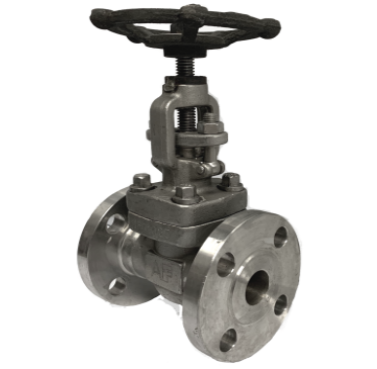
A rising-stem globe valve for throttling and isolation, with ANSI 150# flange ends, 1″–4″ (DN25–DN100), in SS316. Rated 150 PSI, built to API 602 / BS 5352. Graphite packed — built to run part-open, unlike a gate valve.
Tell us the size, the fluid, pressure and temperature — quotes within 2 working hours.
| Ends | ANSI 150# flange |
|---|---|
| Size | 1″–4″ (DN25–DN100) |
| Body | SS316 |
| Pressure | 150 PSI |
| Max temperature | 425 °C |
| Design | API 602 / BS 5352 |
| Inspection | API 598 |
| Stem | Rising stem, handwheel, multi-turn |
| Packing | Graphite |
Throttling duty, ANSI 150# flange ends, built to API 602 / BS 5352.
A rising-stem globe valve in 1″–4″ (DN25–DN100), body in SS316, rated 150 PSI. In a globe valve the flow turns: up through a seat opening, past a disc that lifts squarely off that seat, and down again to leave. That geometry is what lets it be set and held anywhere between shut and fully open.
Two size bands, each with its own drawing and parts list - both are on this page.
Running it part-open is normal service, not abuse. A gate valve held part-open erodes its own seat permanently; a globe valve is built for it.
At 2″ in cast steel a globe is 203 mm face-to-face against 178 mm for the gate. It will not fit the gap a gate valve came out of — measure the run.
Metal seating and a graphite-packed stem, rather than a PTFE seat. That is why globe valves regulate steam and hot oil where a ball valve stops at 150 °C.
As published. We print the catalogue figure rather than inferring one from a sibling variant.
Flow entering beneath the disc, unless the manufacturer says otherwise — it makes the valve easier to open against pressure and keeps the packing out of the throttling stream.
The end type is the first decision and cannot be changed later. Check it against the pipework, not the pressure rating — all ten variants compared.
All photographs of the stocked item, not renders.
A rising-stem globe valve with the handwheel fitted. The stem travels as the valve opens, though not as far as a gate valve’s — the disc does not have to clear the bore.
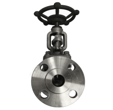
Note the shape: the flow turns twice inside it. That is what makes it controllable, and also why it is longer face-to-face than a gate valve of the same size.
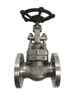
Where the graphite packing sits. Installed flow-under-the-seat, the packing stays out of the throttling stream.
Everything that goes on a purchase order.
| Item | Detail |
|---|---|
| Size range | 1″ to 4″ (DN25 to DN100) |
| End connection | ANSI 150# flange |
| Working pressure | 150 PSI |
| Maximum working temperature | −20 °C to 425 °C as published on the small band, 425 °C on the large |
| Body material | Stainless steel — A182 F316 forged, A351 CF8M cast |
| Trim | F316 disc, stem, gland and pin |
| Design and manufacture | API 602 and BS 5352 |
| End dimensions | ASME B16.5 |
| Inspection and test | API 598 |
| Shell or body test | 3.0 MPa |
| Seal test | 2.2 MPa |
| Gas tightness test | 0.6 MPa |
| Stem | Rising stem, handwheel operated |
| Packing | Graphite |
| Duty | Throttling and isolation — designed to run part open |
| Flow direction | Normally flow under the seat — check the body arrow |
| Stock | Singapore & Malaysia warehouses — out within 24 hours |
Millimetres. Face-to-face L is the gap the valve needs in the run; on a rising-stem globe valve you also need headroom above it, because the stem travels up as it opens.
| Size | Part no | Bore Q | Flange OD D | Bolt circle D1 | Raised face D2 | Face-to-face L | Handwheel W | Height H | Flange thk B | RF height F | Bolts n-z |
|---|---|---|---|---|---|---|---|---|---|---|---|
| 1″ | VL-S-GL-F-150-16 | 18 | 108 | 79 | 51 | 127 | 125 | 203 | 14 | 1.3 | 4-Ø16 |
| 1 1/4″ | VL-S-GL-F-150-20 | 23 | 117 | 89 | 63.5 | 140 | 160 | 224 | 16 | 1.3 | 4-Ø16 |
| 1 1/2″ | VL-S-GL-F-150-24 | 30 | 127 | 98.5 | 75 | 165 | 160 | 260 | 17.5 | 1.3 | 4-Ø16 |
| Size | Part no | Bore d | Flange OD D | Bolt circle D1 | Raised face D2 | Flange thk C | RF height f | Face-to-face L | Bolts n-d1 |
|---|---|---|---|---|---|---|---|---|---|
| 2″ | VL-S-GL-F-150-32 | 51 | 152 | 120.7 | 92.1 | 14.3 | 2 | 203 | 4-Ø19 |
| 2 1/2″ | VL-S-GL-F-150-40 | 65 | 180 | 139.7 | 104.8 | 15.9 | 2 | 216 | 4-Ø19 |
| 3″ | VL-S-GL-F-150-48 | 76 | 190 | 152.4 | 127 | 17.5 | 2 | 241 | 4-Ø19 |
| 4″ | VL-S-GL-F-150-64 | 102 | 230 | 190.5 | 157.2 | 22.3 | 2 | 292 | 8-Ø19 |
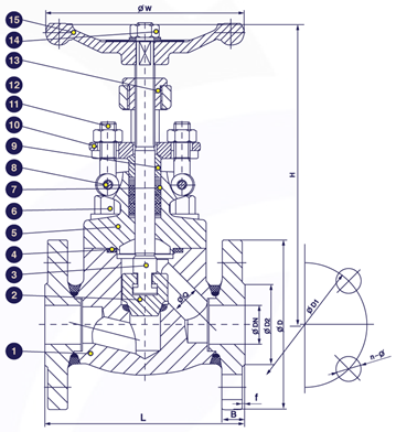
DN25–DN40 (1″–1½″) — 15 callouts, numbered 1 to 15.
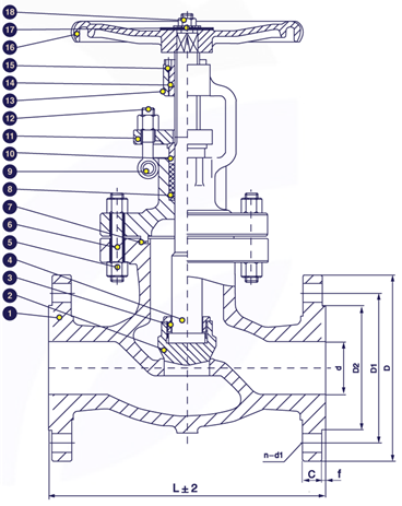
DN50–DN100 (2″–4″) — 18 callouts, numbered 1 to 18.
Callout numbers correspond to the item numbers in the parts lists below — one list per band. The dimension letters are the column headings in the size table above: Q bore, D flange OD, D1 bolt circle, D2 raised face, L face-to-face, W handwheel, H height, B flange thickness, F RF height and n–z the bolt pattern.
Callout numbers are the item numbers in the parts list below, and the dimension letters are the column headings in the size table above. Nothing on the drawing is named only there.
The drawing shows the disc lifting straight off its seat, with the flow turning twice through the body. That is what lets a globe valve be held part open — and why its pressure drop is higher than a gate valve's at full lift.
The larger band has its own catalogue sheet with its own parts list. That is why this page carries two drawings and two bills of material rather than one of each.
This is a catalogue section, not a manufacturing drawing: no tolerances and no material callouts. Order spares by the item numbers in the parts list.
A globe valve is longer face-to-face than a gate valve of the same size — 203 mm against 178 mm at 2″ in cast steel. It will not fit the gap a gate valve came out of. The rising stem also needs clearance above.
Measure the gap in the run against it. On a replacement, measure the valve coming out rather than trusting a drawing — and remember a globe valve of the same size is longer.
Where a letter is ambiguous or mislabelled in the catalogue we say so rather than guess at what was meant.
A valve must not hang on the pipework, and must never be used to pull a misaligned joint together.
ANSI 150# flange — the end type is the first decision and cannot be changed after ordering.
The manufacturer’s item numbers, so a spares order matches the parts list.
| No | Part name | Material |
|---|---|---|
| 1 | Body + Seat | ASTM A182 F316 |
| 2 | Disc | ASTM A182 F316 |
| 3 | Stem | ASTM A182 F316 |
| 4 | Gasket | SS316 + Graphite |
| 5 | Bonnet | ASTM A182 F316 |
| 6 | Bonnet Bolt | ASTM A193 B8M |
| 7 | Packing | Graphite |
| 8 | Pin | ASTM A182 F316 |
| 9 | Gland | ASTM A182 F316 |
| 10 | Gland Flange | ASTM A182 F316 |
| 11 | Gland Bolt | ASTM A193 B8M |
| 12 | Gland Nut | ASTM A194 8M |
| 13 | Yoke Sleeve | ASTM A276 410 |
| 14 | Lock Nut | Carbon Steel |
| 15 | Hardwheel | ASTM A197 |
| No | Part name | Material |
|---|---|---|
| 1 | Body | A351 CF8M |
| 2 | Disc | SS316 |
| 3 | Grand | SS316 |
| 4 | Stem | SS316 |
| 5 | Bolt | A193 B8M |
| 6 | Nut | A193 B8M |
| 7 | Gasket | SS316 + Graphite |
| 8 | Packing | Graphite |
| 9 | Pin | SS304 |
| 10 | Gland Nut | SS316 |
| 11 | Packing Gland | A351 CF8M |
| 12 | Eye Bolt | A193 B8M |
| 13 | Bonnet | A351 CF8M |
| 14 | Stem Nut | A439 D2 |
| 15 | Screw | AISI 1025 |
| 16 | Handwheel | A216 WCB |
| 17 | Gasket | SS316 |
| 18 | Nut | A194 B8M |
They match the callouts on the sectional drawing, so a spares order matches the section rather than a description.
Everything else is a casting or a fastener. On an isolation valve those two surfaces take the duty every time it is closed.
It is also the part that beds in. A small re-tighten of the gland after the first heat cycle is normal.
A bent or scored stem is the usual reason a globe valve will not seat, and it is the part that moves furthest every cycle.
If you need to know what touches your fluid, the whole list is above — we have not summarised it.
Factory proof tests. Not working pressures — the shell test proves the body, the seal test proves the gate against its seat. Do not design to them.
| Item | Value |
|---|---|
| Normal Pressure | 150 PSI |
| Shell Test Pressure | 3.0 MPa |
| Seal Test | 2.2 MPa |
| Gas-Tightness Test | 0.6 MPa |
| Max working temperature | -20°C to 425°C |
| Item | Value |
|---|---|
| Normal Pressure | 150 PSI |
| Shell Test Pressure | 3.0 MPa |
| Seal Test | 2.2 MPa |
| Back Seal Test | 2.2 MPa |
| Gas-Tightness Test | 0.6 MPa |
| Max working temperature | 425°C |
The shell test proves the body and the seal test proves the gate against its seat. They are proof tests well above the working rating, and the valve is not intended to operate there.
That is the number to design to, at 425 °C.
Every variant in this range is inspected and tested to it, so the figures on the other nine pages can be read against these directly.
Running part-open is normal service for a globe valve, not abuse — but the disc and seat still take the whole duty. On a valve that is adjusted often, those two faces are what to ask about.
EN 10204 3.1 is available on request and the castings carry heat numbers — ask with the order, not after the goods arrive.
End type first, then the standard, then the material.
All ten side by side: the comparison table.
Throttling and isolation. A rising-stem globe valve with ANSI 150# flange ends in 1″–4″ (DN25–DN100), body in SS316, rated 150 PSI, built to API 602 / BS 5352. The flow turns past a seat, and the disc lifts squarely off that seat, so flow can be set and held anywhere between shut and fully open.
Yes — that is the point. Running a globe valve part-open is normal service, not abuse. A gate valve held part-open erodes its own seat permanently; a globe valve is built for it.
No. A globe valve is longer face-to-face at the same size — at 2″ in cast steel, 203 mm against 178 mm. You need about 25 mm more in the run. Measure before ordering.
Rated 425 °C, as published. The packing is graphite and the seating is metal, which is what allows the heat — a PTFE-seated ball valve stops at 150 °C.
Flow-under-the-seat unless the manufacturer says otherwise — flow entering beneath the disc. It makes the valve easier to open against pressure and keeps the packing out of the throttling stream.
We hold it in our Singapore and Malaysia warehouses, out of the warehouse within 24 hours of PO. Quotes within 2 working hours.
1″–4″ (DN25–DN100). Part numbers, the bill of materials and the test pressures are all on this page, as printed in the catalogue.
Designed and manufactured to API 602 / BS 5352. Note that nine of the ten variants are tested to API 598, but the JIS 10K cast iron is built to the JIS F7307 / F7400 marine standards instead, so its figures are not directly comparable with the rest of the range.
It is handwheel operated and multi-turn, not quarter turn. Operating torque, turn count and any ISO 5211 pad are not published for this range — settle the actuation arrangement with us rather than assuming a top plate.
No flow characteristic curve and no Cv — which bites hardest here, because this is the throttling valve and the relationship between stem position and flow cannot be read off the sheet. Also no disc type, no operating torque, no ISO 5211 pad and no fire-safe certificate. EN 10204 3.1 is available on request; the castings carry heat numbers.
Related: all globe valves · globe valves · ball valves · all low pressure valves
Baca halaman ini dalam Bahasa Indonesia