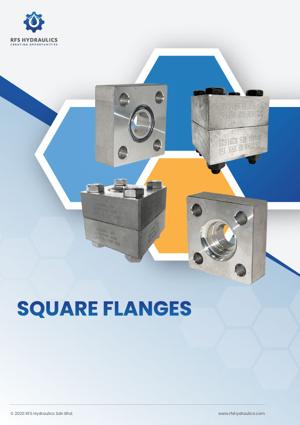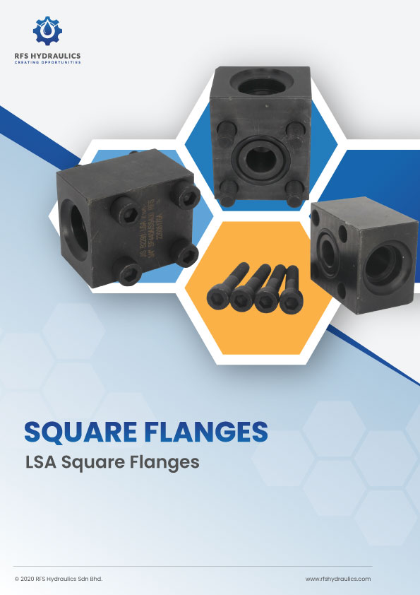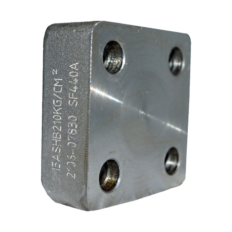
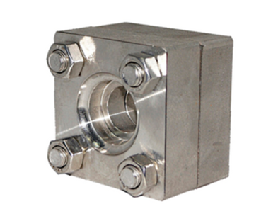
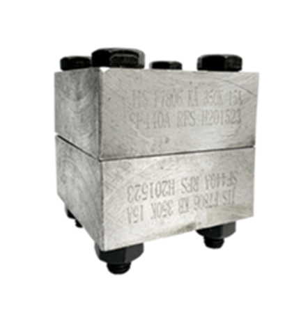
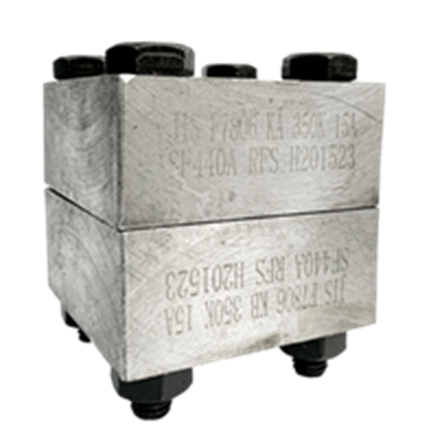
A four-bolt square socket-weld connection, 1/4″ to 6″, in 210, 280 and 350 kgf/cm² — forged SF440A steel or stainless SS316. Supplied as complete sets: A half, B half, O-ring, four bolts and four nuts — not loose halves.
Send the size, series, type, material and pipe schedule — a quote comes back within 2 working hours.
| Size | 1/4″ to 6″ · 8A–150A |
|---|---|
| Standard | JIS B2291 (hydraulic) · JIS F7806 (marine) |
| Pressure series | 210 · 280 · 350 kgf/cm² — rated: 21 / 28 / 35 MPa |
| Configuration | SHA/SHB · SSA/SSB · KA/KB · LSA — A = O-ring side, B = flat side |
| Type | Weld-in (socket weld) · blind |
| Material | Forged steel SF440A (JIS G3201) · stainless SS316 |
| Bolts & nuts | Hex bolts SCM435 (JIS G4105) · nuts S45C (JIS G4051) — four of each |
| O-ring | NBR HS90 · JIS B2401-1B, G and P series |
| Pipe schedule | Bore machined for SCH 40, 80 or 160 |
The full dimension tables for all three series — body, bolt centres, threads and O-ring per size — are in the catalogues below, as printed.
A square flange joins pipe to pipe, or pipe to a component, in a hydraulic system. The body is square, four bolts pass through the corners, and an O-ring in a machined groove does the sealing — not metal-to-metal contact. The load is carried by four bolts at the corners, and the joint can be broken and remade many times — replace the O-ring, inspect the groove, and it is good again. Common on Japanese and Korean-built machinery, shipboard hydraulics, offshore structures and industrial plant.
The MPa figure is the standard’s own, not a unit conversion — a drawing asking for 21 / 28 / 35 MPa is met by 210K / 280K / 350K.
| Aspect | 210K | 280K | 350K |
|---|---|---|---|
| Nominal pressure | 210 kgf/cm² | 280 kgf/cm² | 350 kgf/cm² |
| Rated max working pressure | 21 MPa · 210 bar | 28 MPa · 280 bar | 35 MPa · 350 bar |
| Standard reference | JIS B2291 — titled 21 MPa | JIS F7806 table 1 | JIS F7806 table 1 |
| Type letters | SHA/SHB and SSA/SSB | KA/KB | KA/KB |
| Size range held | 1/2″–4″ (15A–100A) | 1/2″–4″ (15A–100A) | 1/2″–3″ (15A–80A only) |
| Material | SF440A | SF440A | SF440A |
Which series to start from?
| Duty | Start from | Why |
|---|---|---|
| Machinery, presses & plant hydraulics | 210K SHA/SHB to B2291 | What mills and general plant actually run. |
| Shipboard & offshore piping | 280K KA/KB to F7806 | The marine standard — written for pressure plus a salt atmosphere. |
| High-pressure end of marine work | 350K KA/KB | 35 MPa — and it stops at 80A. |
| Drawing calling for a hard 21 / 28 / 35 MPa | 210K / 280K / 350K | The MPa ratings are the standards’ own figures, not conversions. |
| Replacing what is fitted | Whatever the marking says | The installed standard decides. |
| Type | What it is |
|---|---|
| SHA / SHB | The 210K pair to JIS B2291 — hex bolts to JIS B1180/B1182. |
| SSA / SSB | The 210K pair on socket-head cap screws to JIS B1176. |
| KA / KB | The 280K and 350K pairs to JIS F7806. |
| LSA | The long-bolt configuration — its bolts are much longer at the same size (120 mm vs 70 mm at 2B). |
| Blind | Caps a port — same body, bolts and O-ring as the weld-in at that size. |
| A / B | A = the O-ring side (carries the groove) · B = the flat side — one of each per joint; two of the same letter will not seal. |
Three ways of naming the same size: a square flange is quoted in inches, in the JIS A series, or in B — and B is simply the inch figure. The column to look at first is B — the bolt-hole centres. It is the square pitch of the four holes, and it is different in every series at almost every size. All figures in millimetres, as printed in the catalogues.
210 kgf/cm² · SHA / SHB JIS B2291 · SF440A
| Size | Pipe OD | A | B | C | d1 | d2 | e | d3 | f | d4 | Bolt | L | O-ring |
|---|---|---|---|---|---|---|---|---|---|---|---|---|---|
| 1/2″ 15A | 21.7 | 63 | 40 | 22 | 30 | 22.2 | 11 | 32 | 3.5 | 11 | M10 | 60 | G25 |
| 3/4″ 20A | 27.2 | 68 | 45 | 22 | 35 | 27.7 | 12 | 38 | 4.0 | 11 | M10 | 60 | G30 |
| 1″ 25A | 34.0 | 80 | 53 | 28 | 40 | 34.5 | 14 | 45 | 4.0 | 13 | M12 | 70 | G35 |
| 1¼″ 32A | 42.7 | 90 | 63 | 28 | 50/45 | 43.2 | 16 | 56 | 6.0 | 13 | M12 | 70 | G45/G40 |
| 1½″ 40A | 48.6 | 100 | 70 | 36 | 55 | 49.1 | 18 | 63 | 7.0 | 18 | M16 | 95 | G50 |
| 2″ 50A | 60.5 | 112 | 80 | 36 | 65 | 61.1 | 20 | 75 | 7.0 | 18 | M16 | 95 | G60 |
| 2½″ 65A | 76.3 | 140 | 100 | 45 | 80 | 77.1 | 22 | 95 | 9.5 | 22 | M20 | 115 | G75 |
| 3″ 80A | 89.1 | 155 | 112 | 45 | 90 | 90.0 | 25 | 108 | 11 | 24 | M20 | 115 | G85 |
| 4″ 100A | 114.3 | 190 | 140 | 55 | 115 | 115.0 | 34 | 142.5 | 13.5 | 26 | M24 | 145 | G105 |
280 kgf/cm² · KA / KB JIS F7806 · SF440A
| Size | Pipe OD | A | B | C | d1 | d2 | e | d3 | f | d4 | Bolt | L | O-ring |
|---|---|---|---|---|---|---|---|---|---|---|---|---|---|
| 1/2″ 15A | 21.7 | 66 | 43 | 22 | 24 | 22.2 | 12 | 34 | 4.0 | 11 | M10 | 60 | P20 |
| 3/4″ 20A | 27.2 | 72 | 48 | 25 | 30 | 27.7 | 12 | 40 | 4.5 | 11 | M10 | 65 | G25 |
| 1″ 25A | 34.0 | 85 | 58 | 35 | 35 | 34.5 | 14 | 48 | 5.0 | 13.5 | M12 | 85 | G30 |
| 1¼″ 32A | 42.7 | 98 | 68 | 35 | 45 | 43.2 | 18 | 60 | 6.5 | 17.5 | M16 | 90 | G40 |
| 1½″ 40A | 48.6 | 105 | 74 | 40 | 50 | 49.1 | 20 | 66 | 7.5 | 17.5 | M16 | 100 | G45 |
| 2″ 50A | 60.5 | 130 | 90 | 50 | 60 | 61.1 | 20 | 79 | 8.0 | 22 | M20 | 125 | G55 |
| 2½″ 65A | 76.3 | 150 | 108 | 60 | 75 | 77.1 | 25 | 100 | 10.0 | 24 | M22 | 145 | G70 |
| 3″ 80A | 89.1 | 170 | 120 | 65 | 85 | 90.0 | 25 | 114 | 12.0 | 26 | M24 | 160 | G80 |
| 4″ 100A | 114.3 | 190 | 140 | 65 | 115 | 115.0 | 34 | 142.5 | 13.5 | 26 | M24 | 160 | G110 |
350 kgf/cm² · KA / KB JIS F7806 · SF440A
| Size | Pipe OD | A | B | C | d1 | d2 | e | d3 | f | d4 | Bolt | L | O-ring |
|---|---|---|---|---|---|---|---|---|---|---|---|---|---|
| 1/2″ 15A | 21.7 | 68 | 45 | 28 | 24 | 22.2 | 12 | 37.5 | 4.0 | 11 | M10 | 70 | P20 |
| 3/4″ 20A | 27.2 | 82 | 55 | 30 | 30 | 27.7 | 12 | 43.5 | 4.5 | 13.5 | M12 | 75 | G25 |
| 1″ 25A | 34.0 | 95 | 65 | 35 | 35 | 34.5 | 14 | 53 | 5.0 | 17.5 | M16 | 90 | G30 |
| 1¼″ 32A | 42.7 | 100 | 70 | 35 | 40 | 43.2 | 18 | 63 | 6.5 | 17.5 | M16 | 90 | G35 |
| 1½″ 40A | 48.6 | 105 | 75 | 42 | 45 | 49.1 | 20 | 70 | 7.5 | 17.5 | M16 | 105 | G40 |
| 2″ 50A | 60.5 | 132 | 92 | 50 | 55 | 61.1 | 25 | 84 | 8.0 | 22 | M20 | 125 | G50 |
| 2½″ 65A | 76.3 | 160 | 112 | 60 | 65 | 77.1 | 30 | 105 | 10.0 | 26 | M24 | 150 | G60 |
| 3″ 80A | 89.1 | 190 | 130 | 68 | 75 | 90.0 | 30 | 120 | 12.0 | 33 | M30 | 175 | G70 |
Two traps worth knowing. At 32A in the 210K series the socket bore and the O-ring change with the schedule — SCH 40 takes a G45, SCH 80/160 a G40. And at 100A the 210K and 280K flanges share the same 140 mm bolt centres and the same 190 mm body, so the bolt pattern will not separate them — measure the thickness C (55 vs 65 mm), or read the marking.
Everything you need is stamped on the side. The JIS convention: pressure & type, schedule, nominal size, material — e.g. 280K – A – #160 – 80A – SS400.
A is the O-ring side — the half carrying the machined groove. B is the flat side.
If the marking is gone, measure centre to centre between two adjacent bolt holes — the pitch differs per series at almost every size. Watch out: at 40A the 280K and 350K pitches are only 1 mm apart (74 vs 75 mm); at 100A the 210K and 280K share 140 mm — separate them by thickness.
The JIS B2401 G or P number is fixed per size and series — the old O-ring identifies the flange too.
Bolt-hole centres (square pitch, mm) — all three series
| Size | 210K | 280K | 350K | Notes |
|---|---|---|---|---|
| 1/2″ 15A | 40 | 43 | 45 | Separates by 2–3 mm |
| 3/4″ 20A | 45 | 48 | 55 | Separates clearly |
| 1″ 25A | 53 | 58 | 65 | Separates clearly |
| 1¼″ 32A | 63 | 68 | 70 | Close between 280K and 350K |
| 1½″ 40A | 70 | 74 | 75 | 280K and 350K differ by 1 mm |
| 2″ 50A | 80 | 90 | 92 | Separates clearly |
| 2½″ 65A | 100 | 108 | 112 | Separates clearly |
| 3″ 80A | 112 | 120 | 130 | Separates clearly |
| 4″ 100A | 140 | 140 | — | Same pitch; thickness differs (C: 55 vs 65 mm) |
Four hex bolts in SCM435 (JIS G4105) and four nuts in S45C (JIS G4051) come with every set. The thread steps up with the pressure series at the same bore — 65A takes M20 in 210K, M22 in 280K and M24 in 350K.
| Flange size | Thread | L₁ | ℓ₁ | H | S₁ | L₂ · SSA/SSB | L₂ · LSA | ℓ₂ | D | S₂ |
|---|---|---|---|---|---|---|---|---|---|---|
| 1/2″ 15A | M10×1.5 | 55 | 26 | 8 | 17 | 40 | 60 | 26 | 16 | 8 |
| 3/4″ 20A | M10×1.5 | 55 | 26 | 8 | 17 | 40 | 65 | 26 | 16 | 8 |
| 1″ 25A | M12×1.75 | 75 | 30 | 10 | 19 | 55 | 75 | 30 | 18 | 10 |
| 1¼″ 32A | M12×1.75 | 75 | 30 | 10 | 19 | 55 | 90 | 30 | 18 | 10 |
| 1½″ 40A | M16×2 | 90 | 38 | 13 | 24 | 70 | 105 | 38 | 24 | 14 |
| 2″ 50A | M16×2 | 90 | 38 | 13 | 24 | 70 | 120 | 38 | 24 | 14 |
| 2½″ 65A | M20×2.5 | 110 | 46 | 16 | 30 | 90 | 150 | 46 | 30 | 17 |
| 3″ 80A | M22×2.5 | 115 | 50 | 18 | 32 | 90 | 160 | 50 | 33 | 17 |
The LSA bolt is much longer at the same size — 120 mm against 70 mm at 2B — so standard bolts will not reach on an LSA flange. One caveat on 80A, stated plainly: the table above is from our square flange specification sheet and gives M22×2.5 at 3B; the 210K series dimension table gives M20 at 80A — state the series when you order and we send the right bolts. Torque the four evenly and in a cross pattern; snug all of them before bringing any one up to full value.
O-ring size by series JIS B2401 · NBR HS90
| Flange size | 210K | 280K | 350K |
|---|---|---|---|
| 1/2″ 15A | G25 | P20 | P20 |
| 3/4″ 20A | G30 | G25 | G25 |
| 1″ 25A | G35 | G30 | G30 |
| 1¼″ 32A | G45 / G40 | G40 | G35 |
| 1½″ 40A | G50 | G45 | G40 |
| 2″ 50A | G60 | G55 | G50 |
| 2½″ 65A | G75 | G70 | G60 |
| 3″ 80A | G85 | G80 | G70 |
| 4″ 100A | G105 | G110 | — |
The O-ring size is not the same across the series at a given bore. The G series follows a simple rule: inside diameter = the G number minus 0.6 mm, section 3.10 mm — G25 = ID 24.40 · OD 30.60; G60 = ID 59.40 · OD 65.60; G110 = ID 109.40 · OD 115.60 mm.
NBR HS90 compound properties
| Property | Value | Test standard |
|---|---|---|
| Hardness | Shore A 85 ± 5 | DIN 53505 |
| Density | 1.28 g/cm³ | — |
| Tensile strength | 16 N/mm² | DIN 53504 |
| Elongation at break | 140 % | DIN 53504 |
| Compression set, 70 h at 100 °C | 19 % | ASTM D395B |
| Tear strength | 8 N/mm | DIN 53507 |
| Abrasion | 130 mm³ | DIN 53516 |
| Application temperature | −30 °C to +100 °C | — |
| Volume change, ASTM oil #1 | −8 % | DIN 53521 |
| Volume change, ASTM oil #3 | +12 % | DIN 53521 |
| Volume change, water at 100 °C | +2.5 % | DIN 53521 |
Not resistant to: brake fluids, aromatic compounds such as benzole, esters, ketones and amines, strong acids and alkaline solutions — for those fluids, ask for Viton (FKM).
SF440A — chemical composition (% by weight) example heat HZ23815, from a 3.1 certificate
| C | Si | Mn | S | P | Cr | Ni | Cu | |
|---|---|---|---|---|---|---|---|---|
| Specified max | 0.60 | 0.50 | 1.20 | 0.035 | 0.030 | 0.30 | 0.30 | 0.30 |
| Specified min | — | 0.15 | 0.30 | — | — | — | — | — |
| Heat HZ23815 · test 1 | 0.25 | 0.23 | 0.60 | 0.024 | 0.017 | 0.17 | 0.23 | 0.18 |
| Heat HZ23815 · test 2 | 0.24 | 0.23 | 0.61 | 0.022 | 0.018 | 0.18 | 0.22 | 0.18 |
SF440A — mechanical properties
| Yield (N/mm²) | Tensile (N/mm²) | Elongation (%) | Reduction of area (%) | Hardness (HB) | Visual & dim. | |
|---|---|---|---|---|---|---|
| Specified min | 225 | 440 | 24 | 55 | 121 | — |
| Specified max | — | 550 | — | — | — | — |
| Heat HZ23815 · test 1 | 264 | 492 | 31.0 | 67 | 144 | OK |
| Heat HZ23815 · test 2 | 266 | 489 | 31.3 | 66 | 143 | OK |
What is on the part, and why it matters: the standard (B2291/F7806) fixes the dimensions and the pressure series · the type & series (e.g. SHB, 210K) tell you the half you are holding and the pressure it is rated for · the nominal size (e.g. 15A) with the schedule fixes the bore · the material (SF440A) ties the part to the grade on the certificate · and the heat number — the one that matters most — ties the individual flange in your hand back to a specific 3.1 certificate. A flange with no heat number cannot be traced, whatever paperwork arrives with the box.
One A half and one B half, same size and same series.
Square the pipe, seat it in the socket and weld round the outside. Never weld with the O-ring fitted.
Remove weld spatter; check the face and groove for nicks or contamination.
Fit the O-ring into the groove in the A half, bring the halves together and snug all four bolts by hand in a cross pattern.
Work the four bolts up in stages, opposite corners each time. Note: unlike SAE J518, neither JIS B2291 nor F7806 publishes a tightening torque — ask us if you need guidance.
Between them the two catalogues cover weld-in and blind in all three series, both type families, and the O-ring groove dimensions. Dimensions and part numbers are in the catalogues; stock and price are not — send us the list and we confirm both. More catalogues in the catalogue library.
It joins pipe to pipe, or pipe to a component, inside a hydraulic system. The body is square, four bolts pass through the corners, and an O-ring in a machined groove does the sealing rather than metal-to-metal contact. It gives a compact high-pressure joint that can be broken and remade without disturbing the pipe run.
Two separate standards. JIS B2291 is the hydraulic square flange standard — machinery, presses and plant; our 210K SHA/SHB range is marked to it. JIS F7806 is the shipbuilding standard, written for piping onboard ships and offshore structures — it covers the 280K and 350K KA/KB ranges. Dimensions and pressure series differ; halves are not interchangeable between them. Where the flanges go into equipment essential to the ship’s safety or propulsion, confirmation from the classification society is still required.
The nominal working pressure in kgf/cm² — the legacy label the trade still orders by. The rating the standards state is a round SI figure: 21 MPa (210 bar), 28 MPa (280 bar), 35 MPa (350 bar). So a drawing asking for a hard 21 MPa is met by 210K — do not convert the kgf/cm² label and talk yourself into the next series up.
A is the O-ring side — the half carrying the machined groove (our catalogue also calls it the counter-flange). B is the flat side. The two are handed and ordered as a pair — two of the same letter will not seal. SH, SS, K and LS denote the type family, which goes with the pressure series and the standard.
No. The bolt-hole centres differ between series at almost every size — at 25A: 53, 58 and 65 mm for 210K, 280K, 350K — so the bolts will not line up, and the O-ring groove differs too. The exception is 100A, where 210K and 280K share the same 140 mm pitch and 190 mm body, so they can be bolted up by mistake — separate them by thickness (C = 55 mm in 210K, 65 mm in 280K) or by the marking. Getting it wrong puts a 210 bar flange in a 280 bar line.
No, in no size. An SAE J518 flange is round-bodied, rated in psi classes (Code 61/62), dimensioned in inches. A JIS square flange is square-bodied, rated in kgf/cm², dimensioned in millimetres. The bolt patterns, ports and O-rings are all different. We stock both lines — tell us which one the existing installation uses.
NBR HS90 to JIS B2401-1B, in the G series for most sizes (the P series at 15A in the higher pressure ranges). The size is fixed by the flange and differs across the series: 50A takes G60 in 210K, G55 in 280K, G50 in 350K. Replace the O-ring every time the joint is broken. Viton (FKM) is available where the fluid or temperature rules out nitrile.
SF440A, a forged carbon steel to JIS G3201 — the same grade across all three pressure series; the higher series carry more pressure through heavier sections and larger bolts, not a different steel. SS316 is available in any series for deck, splash-zone, chemical or washdown service. In ASTM terms SF440A sits with the SA-105 grades.
Yes — 1/4″ to 6″ across all three series, as complete sets (A half, B half, O-ring, four bolts, four nuts), held in our regional warehouses in Singapore and Malaysia. Goods leave the warehouse within 24 hours of your PO, with the delivery schedule to your city confirmed in the quotation. An EN 10204 3.1 certificate follows the forging.
State seven things: the size (1/4–6″ or the A size); the series (210K/280K/350K); the type letter (SHA/SHB, SSA/SSB, KA/KB, LSA); weld-in or blind; the material (SF440A/SS316); the pipe schedule (SCH 40/80/160 — at 32A in the 210K series the schedule also changes the O-ring); and the application (B2291 or F7806). Send it via WhatsApp ★ Google reviews ▶ YouTube channel or the contact form — a quote comes back within 2 working hours.
See also all flanges, SAE flanges, hydraulic steel tubes, and SS316 pipe — or read this page in Bahasa Indonesia.